Basic Concepts. This section will give you an overview of the basic concepts you need to understand to write 3D programs in EXPL.
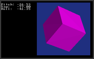
1. The Viewer. Accelerated 3D graphics are displayed in a window called a Viewer. The Viewer is a rectangular area in the EXPL console that can display 3D graphics. It can be hidden or displayed, and can be any size or place on the screen. Ordinary graphics and text can be displayed anywhere outside the Viewer window. This enables you to mix 3D graphics and text with ordinary graphics and text. |
|
2. 3D Objects. The Viewer displays 3D objects of various types. Currently, the objects consist of 3D frames, 3D meshes, 3D strings and 3D lines. Each of these objects can be positioned, rotated and displayed independently. Here is a description of each object type:
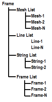
A. Frames. A Frame is an invisible object designed to hold other objects. It can hold meshes, lines, strings and other frames.
Hierarchy. Frames enable you to organize 3D objects in a hierarchical structure where the objects have a specific relationship to each other. Every object gets its base position and rotation from the object above. If you move or rotate a parent frame, all child objects will move in exactly the same way. On the other hand, if you move a child object, the parent is unaffected. This is useful for creating 3D scenes where there is a relationship between the various objects. For example, you could create a model of the solar system where all the planets are children of the sun and move when the sun moves while each planets is independent and moves relative to the other planets or the sun.
Because of this structure, each object has a parent object that must be a frame.The Viewer always has one Base frame to which more frames, meshes, strings and lines can be added. All parent objects must be frames and only frames can hold objects. |
|
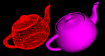
B. Meshes. A Mesh is a collection of three-dimensional triangles that is used to make 3D models of real-world objects. Each triangle forms a face, and if you group together a number of faces, they can be used to form surfaces that simulate the appearance of real-world objects. To make the meshes more realistic, the triangle faces can be smoothed using "normals" to control the way light bounces off the surface. This changes the appearance of a surface from faceted to completely smooth. |
|
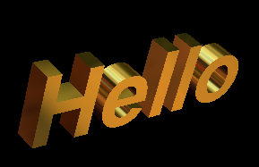
C. Strings. A 3D String is used to construct and display extruded, three-dimensional text. The strings can be displayed using any font that is available on the computer. You can also set the 3D depth of the extrusion of the string. Once a string has been constructed, 3D strings behave just like meshes. They can be colored, textured, moved, rotated and displayed in various modes. |
|
D. Lines. Lines are objects that consist of 3D line segments. Each line is specified by a beginning and ending 3D point. You can set the thickness of the lines, and each line can be drawn in a different color.
You can also use lines as the basis for Stroke Fonts. Unlike the 3D strings, stroke fonts consist of text drawn with a series of single line segments. Stroke fonts are more appropriate for labeling things in a scene than the 3D strings described above, which are more decorative in purpose. |
|
7. Object Handles. Each 3D object is identified by an integer value called a handle. When you create a 3D object, you are given a handle for that object. With the handle you can perform a variety of operations on the object associated with the handle. For example, you can add triangles to a mesh using its handle. Since a handle can be associated with different types of 3D objects, only certain operations can be performed on certain handles. For example, you cannot add a triangle to a frame handle. There are two preset handles:
-1 = The Base Frame
-2 = Represents the entire scene.
8. Normals. Normals are special vectors that are placed at the vertices of each triangle. Normals are used to help smooth a mesh's surface. This reduces the number triangles needed to display an object.
Normals are generally set to be at roughly right angles to the face of the triangle.They are used by the Viewer to determine how light will reflect off the surface of the triangle. Depending on how the normals are set, the edges between faces can appear as a sharp line or smooth rounded edge.
|
|
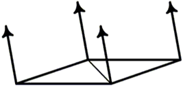
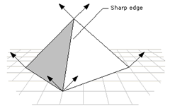
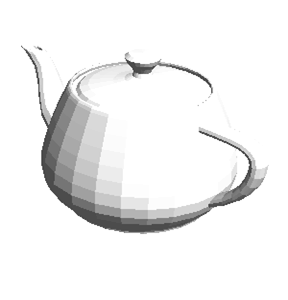
If the normals are at right angles to each triangle, the edges between triangles will appear as a sharp edge. This is illustrated by the left-hand drawing below. Here, each triangle has three separate normals |
|
Normals At Right Angles to Each Face |
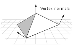
Normals Averaged Between Adjacent Faces |
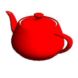
On the other hand, if the normals are set to the average of the angles of the faces around the vertex, the edges will appear smooth. This is illustrated by the right-hand drawing above. Because each normal is the average of its neighbors, each triangle uses the exact same normal as its neighbor. |
|
|
|
The two images above illustrate what the same object looks like using different normals. The image on the left has normals that are at right angles to each face. That gives the object a faceted look. In order to smooth the surface without using normals, you'd need many more triangles. The image to the right shows what happens if you use normals that average the angles between faces. You can set normals using the Set3DNormals intrinsic. |
|
9. Colors. In EXPL 3D graphics, colors are represented by 32-bit integer values. Each byte of the 32-bit integer holds a red, green, blue and alpha value in that order from low byte to high byte (Intel, little-endian format.) In other words, as a hex integer, the values would be represented as: $AABBGGRR. You can convert RGB and alpha values to a 32-bit integer using the RGBToColor intrinsic.
