Morphing is a word that describes a
mathematical process used to warp images based on the on the positions
of pairs of lines. Normally, the process is performed on bitmap images.
The process compares the positions of the line pairs and moves the
pixels based on the differences in the positions of the lines. For
example, if the second line is rotated relative to the first, the pixels
near the line will be rotated.
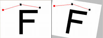
| For example, in the images to the
right there two pairs of lines. In the second image, the lines
have been rotated a few degrees clockwise. As a result, the
second image is rotated the same amount. You will also notices
that since lengths and relative positions of the lines has not
changed, the image is not warped. |
|
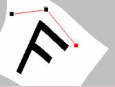
| This image shows what happens if
the lines are stretched and rotated relative to each other. In
this case, the image is warped, with some parts compress and
some parts stretched. This process can also be applied to
cave drawings by using the passage shot lines as the line-pairs. So, for
example, if the shot lines move or change, the program will have
information about how to adjust the cave drawing. Instead of moving
pixels, the program moves elements (vectors) that make up the line
drawing. In this way, hand-drawn elements such as the passage walls, and
floor details are moved, rotated, scaled, stretched, and compressed
based on the changes in the cave data. |
|
The standard Morphing technique was pioneered by in a paper by
Thaddeus Beier and Shawn Neely in a paper called "Feature-Based Image
Metamorphosis". (It is currently available on line here:
http://www.hammerhead.com/thad/morph.html). David McKenzie pioneered
the concept of using this morphing technique in cave maps with his Walls
program.
The technique measures the position of an object relative to a survey
line and tries to maintain that relationship if the line moves. Since
there are dozens or hundreds of lines in a cave survey, all the lines
may have an effect on each object. If all the lines move together, then
all the objects will move exactly like the lines. For example, if the
cave is moved, the objects will move exactly the same amount.
On the other hand, there may be times when all the survey lines do
not move in exactly the same way. For example, if an error has been
corrected in the survey, some lines will move and others will not. If
this happens, the program has to sort out which lines effect which
objects. This is done with a weighting each line and averaging the
effects of all the lines. The weights are based on the Length of
the Line, the Distance from the object and Precision required. Here is
the weighting equation:
Weight = ((Length ^ P) / (A + Distance))^B
Where:
Length = Length of the Line
Distance = Distance of Object From Line
A = Controls Precision
P = Control Effect of Line Length
B = Control Effect of Distance.
For more detailed information about the process, refer the article
described above. |