|
Understanding Declination and Convergence
Declination. Caves are usually surveyed with a magnetic compass. Magnetic
compasses don't point at the true North Pole. They point at the magnet North
Pole. Today, the magnetic North Pole is about 250 miles south of the North Pole.
That means that a compass reading will be offset from True North. The amount of
the offset varies according the place on the Earth where the reading was taken. This offset is
called "Declination."
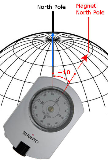
| The image to the right illustrates how
declination works. In this example, the Magnet North
Pole is 10 degrees to the right of the True North Pole. If
the compass is aimed right at the Magnetic North Pole,
the compass will read zero. However, since the
declination is 10 degrees, the compass is really
pointing 10 degrees to the right of the North Pole. That
makes the real azimuth 10 degrees.
From this we can work out the mathematics for
handling declination. You simply add the declination to
the compass reading to get the vlaue relative to True
North. Here's the equation:
TN = CR + Declination.
TN = True North Reading
CR = Compass Reading.
As another example, if the compass reading was 25
degrees and the declination was 5, then the actual
bearing is 30 degrees relative to True North.
30 = 25 + 5
|
|
| UTM Convergence. UTM coordinates
work by mapping a square grid on the surface of the
globe. Because of the fact that the globe is a curved
surface, the lines of Longitude curve toward the edges
of the UTM zone.
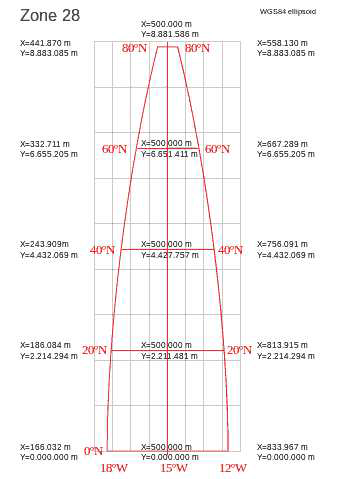
The image to the right shows a typical UTM zone. The
Grid lines are in gray and Longitude lines are in red. The
line down the center is called the "Central Meridian and
it does not curve. However, the further you move
away from the Central Merian, the more the lines curve.
As you can see from the drawing, the lines curve in such a
way that they converge at the North Pole. This is where
the word "Convergence" comes from.
Convergence is the measure of the angle between the
red longitude lines and the gray Grid lines. On the east
side of the grid, the angle from the Longitude line to
the Grid line is positive. Likewise, on the west side
the angle is negative.
Once you apply declination to a cave survey, the
lines in the cave are aligned to True North. If you plot
the cave survey on a map that uses UTM, the cave will
not be aligned to the UTM grid and the location of the
passages will be out of position relative to features on
the map. |
 |
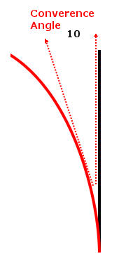
| To solve this problem, you can apply
the UTM Convergence angle to a cave survey. The example
to the right shows how this is done. Again,
convergence angle is measured from the red Longitude
line to the black Grid line. Since the angle is
clockwise, the value is positive. In this example, the
convergence angle is +10 degrees.
If you had a passage whose azimuth measured zero
degrees, the passage would be aligned to the left-hand
dotted red line. Since the dotted red line is counter
clockwise from the black line, its angle is minus 10
degrees relative to the grid line. As a result, you
always subtract the convergence angle from the azimuth.
The formula is thus:
GN = TV - Convergence.
GN = Grid North Reading
TV = True North Value.
As another example, if the True North value was 5
degrees and the convergence was 10 degrees, the Grid
North value would be -5 degrees:
-5 = 5 - 10
|
 |
| Convergence Conventions.
Convergence can be measured in two difference ways.
These two methods are called 1) the Gauss-Bomford
convention and 2) the Survey convention.
Here is a description of each one. 1.
Gauss-Bomford Convention. In this convention, the
angle of the lines of longitude is subtracted from the
grid lines. This means that in the Northern Hemisphere,
positions to the East of the Central Meridian have
positive convergence angles and positions west of the
Meridian have negative angles. Positions in the Southern
Hemisphere have the opposite signe.
This is the most commonly used method of deriving the
Convergence angle. It is the method used in Compass and
the Geographic Calculator returns convergence values
calculated in this way.
2. Survey Convention. In this convention, the
angle of the grid lines is subtracted from the lines of
longitude. As a result, the Convergence angle has the
opposite sign of the Gauss-Bomford convention. This
method is only used in Australia and New Zealand.
For more information on these two conventions, check
out this document:
http://www.iogp.org/pubs/373-21.pdf |
|