|
|
|
Setting Morph
Parameters. |
| E.
Setting Morph Parameters. The program
uses a mathematical process called "Morphing" to adjust the
drawings. (Click
here for technical details of the morphing process.)
You can control certain aspects of the morphing process by
setting the "Morph Parameters." |
| There are three
morphing parameters. The controls to set them appear on at the
bottom of the right hand panel. The default parameter will work
well under most circumstances, but there are a few situations
where you might need to adjust them. Here is a description of
each control: |
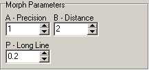 |
| 1. Precision.
(Range = 0.01 to 1.) This setting
controls how precisely elements near a shot line are positioned.
Very small numbers force the elements to track very precisely,
but it may cause more abrupt warp between one part of the map
and another. Larger numbers produce smoother warping of
the map, but items may drift away from the ideal position. I
rarely need adjust this value. |
| 2. Distance.
(Range = 1 to 100). This setting
controls how far the effects of a survey line travels. If the
number is small, every element is effect by all the lines. If
the number is large, only the nearest lines have any effect on
an element.
Changing this is useful under certain specific
circumstances. For example, occasionally two nearby lines may
pull on the elements between. In the example to the right, an
error correction separated the branch passage from the main
trend. Elements between the branches tend to be pulled in both
direction. When first morphed this passage, the passage wall on
both passages were pulled toward the center. |
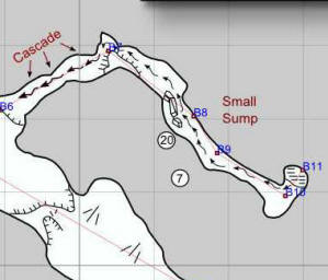 |
| To fix the problem,
I increased the value to 14, which cleared up the problem. In
theory you could use much larger value, but eventually the
program would fail to warp close passages. |
| 3. Length. (Range
= 0 to 1) This setting controls the
effect of long lines as compared with short lines. If the value
is small, then all lines have the effect. If the value is
larger, longer lines have stronger effect than short lines. For
caving purposes, you generally don't want a longer line to
dominate. For example, you wouldn't want the effect of a
100-foot to reach far into the nearby surveys because it might
distort an unrelated passage. In fact, we want nearby passages
to dominate, so we want to de-emphasize longer passages.
|
|
|
|
|